Introduction
A fluidized bed is a state of a mixture of solid particles and fluid, which is widely used in many modern technologies for the efficient implementation of various physical and chemical processes. Fluidized beds are widely used to process large volumes of fluid. The solid particles which are present in the fluidized bed could be fluidized by either gas or liquid, upon which the whole mixture starts to behave like a liquid. The chief advantage of a fluidized bed system is that the particles are well mixed leading to low-temperature gradients. This means that fluidized beds are likely to have high heat and mass transfer rates between the fluid phase and solid phase. For this reason, fluidized beds are widely used in environmental, chemical, and process industries; the applications can be roughly divided into two categories, i.e.,
- physical operations, such as transportation, heating, absorption, mixing of fine powder, etc. and
- chemical operations, such as reactions of gases on solid catalysts and reactions of solids with gases etc.
Despite the simple setup, fluidized beds show a variety of complex flow regimes. Gas-fluidized beds usually are unstable and exhibit bubbling instabilities, however intervals of stable fluidization have also been observed. Liquid-fluidized beds are more stable and a wider range of flowrates gives rise to homogeneous fluidization, in particular for low Reynolds number flow.
A liquid-solid fluidized bed, which is used in fluidized-bed heat exchangers made by Taprogge, is an ensemble of solid particles that are suspended (fluidized) by an upward flowing liquid. The benefits of liquid−solid fluidization are low and constant pressure drop when operating above the minimum fluidization velocity (see the last section), optimal mixing (contacting) between the solid particles and the liquid, good heat and mass transfer rates, and an adjustable porosity of the fluidized bed by changing the fluid velocity. However, the operation of a fluidized bed is not always free from problem. Their hydrodynamic behavior can sometimes show unwanted changes, e.g. due to agglomeration or particle settling process. Hence, the prediction of the hydrodynamics in fluidized beds of particles is of fundamental importance in designing the equipments and in evaluating the efficiency of physical and/or chemical operations.
From a hydrodynamic standpoint, a fluidized bed exhibits a rich variety of dynamic effects at different spatial and temporal scales. In order to be able to improve the fluidized beds design, it desired to understand, predict and evaluate the hydrodynamics behaviuor of particles as a vital foundation for optimizing the operation and design of solid-liquid fluidized beds units.
It is generally agreed that the terminal settling velocity of the particles, the minimum fluidization velocity and its corresponding bed voidage and the velocity voidage relationship are the most important parameters of fluidization technology. In this document, the most important hydrodynamic characteristics of a solid – liquid fluidized system, which is relevant to Klaren technology, are reviewed / discussed.

Fluidization Regimes
When a fluid is passed downwards through a bed of solid particles, no relative movement between the particles takes place, unless the initial orientation of the particles is unstable, and where the flow is streamline, the pressure drop across the bed is directly proportional to the rate of flow, although at higher rates the pressure drop increases more rapidly. This type of flow is classified as flow of fluid through a granular bed and/or packed bed which is not discussed in this document.
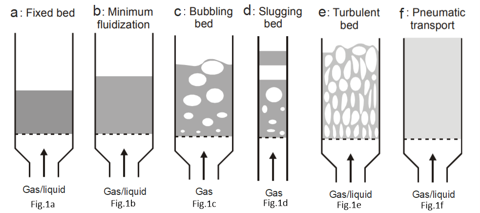
Upward fluidization in the fluid-solid system is controlled by the fluid flow rate. When a fluid is passed upwards through a bed of solid particles, the pressure drop is the same as that for downward flow at relatively low rates. When, however, the frictional drag on the particles becomes equal to their apparent weight — that is, the actual weight less the buoyancy force — the particles become rearranged, thus offering less resistance to the flow of fluid, and the bed starts to expand with a corresponding increase in voidage. This process continues with increase in velocity, with the total frictional force remaining equal to the weight of the particles, until the bed has assumed its loosest stable form of packing. In this condition, some of particles are vibrating, but still the bed is within the same height as the bed at rest. This is called a fixed bed (see Fig. 1a).
With increasing fluid velocity, the superficial velocity of liquid increases and a point is reached where the individual particles separate from one another and become freely supported in the fluid. At this stage, the drag force imparted by the upward moving fluid equals the weight of the particles, and the voidage of the bed increases slightly: this is the onset of fluidization and is called minimum fluidization with a corresponding minimum fluidization (or superficial) velocity, Umf. In this condition, the bed is described as fluidized, as shown schematically in Fig 1b. In this regime, there exists a clear boundary between the bottom dense region and the top freeboard region. Within this regime, an increase in the liquid flow rate causes the dense phase to expand more and raises the dense-dilute phase boundary. Further increase in the velocity causes the particles to separate still further from one another, although the pressure difference remains approximately equal to the weight per unit area of the bed. In practice, the transition from the fixed to the fluidized bed condition is not uniform, mainly due to irregularities in the packing and, over a range of velocities, fixed and fluidized bed regions may co-exist. In addition, with gases, surface-related forces give rise to the formation of conglomerates of particles through which there is a little flow and, as a result, much of the gas may pass through the bed in channels. This is an unstable condition, since the channels that offer a relatively low resistance to flow tend to open up as the gas flowrate is increased, and regions of the bed may remain in an unfluidized state even though the overall superficial velocity may be much higher than the minimum fluidising velocity.
Up to this point, the system behaves in a similar way with both liquids and gases, although at high fluid velocities, there is usually a fairly sharp distinction between the behaviour of the two systems. With a liquid, the bed continues to expand as the velocity is increased and it maintains its uniform character, with the degree of agitation of the particles increasing progressively. This type of fluidization is known as particulate fluidisation. With a gas, however, uniform fluidisation is frequently obtained only at low velocities. At higher velocities two separate phases may form—a continuous phase, often referred to as the dense or emulsion phase, and a discontinuous phase known as the bubble phase. The fluidisation is then said to bubbling type (see Fig. 1c).
At much higher velocities, the bubbles tend to break down—a feature that leads to a much more chaotic structure. When gas bubbles pass through a relatively high-density fluidized bed, the system closely resembles a boiling liquid, with the lean phase corresponding to the vapor and the dense or continuous phase corresponding to the liquid. The bed is then often referred to as a boiling bed, as opposed to the quiescent bed usually formed at low flowrates. As the gas flowrate is further increased, the velocity relative to the particles in the dense phase does not change appreciably, and streamline flow may persist even at very high overall rates of flow because a high proportion of the total flow is then in the form of bubbles. At high flowrates in deep beds, coalescence of the bubbles takes place, and in narrow vessels, slugs of gas occupying the whole cross-section may be produced. These slugs of gas alternate with slugs of fluidized solids that are carried upwards and subsequently collapse, releasing the solids, which fall back, as shown schematically in Fig. 1d.
Finally, when a bed of fine particles is fluidized at sufficiently high velocities (well above the minimum fluidisation), the terminal velocity of the solids is exceeded, the bed surface becomes diffused and essentially disappears. At this stage, the velocity exceeds the terminal velocity of the particles. The upper surface of the bed disappears and, instead of bubbles, one observes a turbulent motion of solid clusters and voids of gas of various sizes and shapes. Beds under these conditions are called turbulent beds that have high heat and mass transfer rates (see Fig. 1e). Further increase in the fluid velocity results in nearly complete entrainment of particles, requiring recycling or continuous feed of the particles into the bed. This is a dilute or lean-phase fluidized bed state with pneumatic transport of solids, shown schematically in Fig. 1f.
In order to differentiate between the conditions leading to particulate or aggregative fluidization, Wilhelm and Kwauk suggested using the value of the Froude number as a criterion: 𝑭𝒓=𝑼𝒎𝒇𝟐/𝒈𝒅𝒑
where Umf is the minimum fluidization/superficial velocity of fluid at which fluidization occurs, dp is the diameter of particles and g is the acceleration due to gravity. Note that superficial velocity is equal to volumetric flow of the fluid divided by its total cross-sectional area of the particle bed. At values of a Fr < 1, particulate fluidization normally occurs and, at Fr > 1, aggregative fluidization takes place. Much lower values of the Froude number, Fr ≪ 1, are encountered with liquids because the minimum velocity required to produce fluidization is less. A theoretical justification for using the Froude number as a means of distinguishing between particulate and aggregative fluidization has been provided in.
Pressure Drop in Fluidized Beds
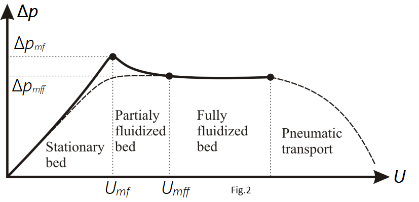
When a fluid flows slowly upwards through a bed of fine particles, the flow is streamline and a linear relation exists between the pressure drop and flow rate. If the pressure across the whole bed is plotted against the fluid velocity, using logarithmic coordinates as shown in Fig. 2, a linear relation is obtained, up to the point where expansion of the bed starts to take place (i.e. for U < Umf), although the slope of the curve then gradually diminishes as the bed expands and its porosity increases. As the velocity approaches the minimum fluidizing velocity (U = Umf), the bed starts to expand and when the particles are no longer in physical contact with one another, the bed is fluidized. The pressure drop then becomes lower because of the increased porosity and, consequently, the weight of particles per unit height of bed is smaller. As the velocity is further increased (i.e. for U > Umf), the pressure drop passes through a maximum value and then falls slightly and attains an approximately constant value that is independent of the fluid velocity. With further increase in the velocity (i.e. for U ≫ Umf), the pressure drop decreases as the slugging transitions to pneumatic transport wherein the whole fluid solid system will flow with the same pressure value as that of inlet pressure.
In a fluidized bed, the total frictional force on the particles must equal the effective weight of the bed. Thus, the additional pressure drop across the bed attributable to the layout weight of the particles is given by:
−𝚫𝒑=(𝟏−𝒆)(𝝆𝒑−𝝆𝒇)𝒈𝒉 (2)
where g is the acceleration due to gravity, ρp and ρf are the densities of the particles and the fluid, respectively and h is height of the fluidized bed (which is equivalent with the height between the two pressure measuring points in practical tests). Also, e is the bed porosity (or voidage), i.e that refers to the ratio of void volume (i.e. the fluid spaces between the particles) to total volume of the bed.
The pressure drop trend can be explained in terms of porosity as well. As we increase the velocity of the fluid, the drag caused by the fluid on the particles increases. Incipient fluidization occurs when the drag force balances the weight of the particles. The particles begin to lift and are barely fluidized. Beyond this, as we increase the velocity of the fluid, the bed of solids expands which leads to rise in bed porosity. Increase in bed porosity decreases the overall drag until it is again balanced by the total weight exerted by the solid particles. now, even if you increase the velocity which in turn will cause rise in the bed height, there will be a substantial rise in bed porosity too, which means, value of h will increase but value of (1 – e) will decrease and overall Δp will remain the same.
As the upward velocity of flow of fluid through a packed bed of uniform spheres is increased, the point of incipient fluidisation is reached when the particles are just supported in the fluid. The corresponding value of the minimum fluidising velocity, Umf, which is an important parameter involved in the design of the fluidized bed systems. Determination of Umf helps in finding the minimum superficial liquid velocity needed for keeping the particles as fluidized bed.
The minimum fluidization velocity can be obtained by applying some theoretical/empirical models such as the so-called Ergun equation that relates the Galileo number (also known as the Archimedes number) to the Reynolds number in terms of the voidage emf at the incipient fluidisation point. However, the minimum fluidizing velocity, Umf, may be expressed in terms of the free-falling velocity of the particles in the fluid as well.