Self-cleaning heat exchangers by applying a fluidized bed
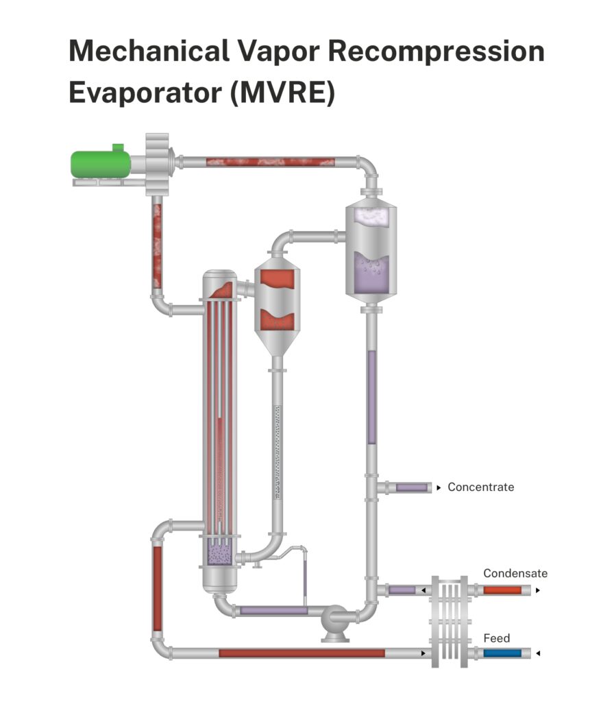
The operating principle of the self-cleaning fluidized bed heat exchangers is based on the circulation of solid cleaning particles through the tubes of a vertical shell and tube heat exchanger. The fouling liquid flows upward through the tube bundle of the heat exchanger that incorporates specially designed inlet and outlet channels. In the inlet channel the solid particles are fed to the fluid using a proprietary distribution system to ensure a uniform division of particles over all the tubes. The particles (mostly stainless steel or ceramic particles with a size between 1.6 and 4 mm) are fluidized by the upward flow of liquid, where they create the mild scouring effect on the wall of the heat exchanger tubes, thereby removing any deposit at an early stage of fouling formation. After the tube bundle the particles disengage from the liquid in the separator and are returned to the inlet channel through an external down comer, and the cycle is repeated.
To control the amount of particles fed to the inlet, a part of the inlet flow to the heat exchanger is used to push the particles from the down comer into the inlet channel.
With the self-cleaning heat exchanger many types of fouling deposits can be effectively handled, whether hard or soft, originating from biological, crystallization, chemical or particulate fouling mechanism, or a combination of these.
Click on the image to enlarge
Figure 1
MVR Evaporator versus MEE from the perspective of energy efficiency
MVR Evaporator requires significantly less energy than a Multi Effect Evaporator (MEE). For the latter, the energy consumption in the form of fresh steam is highly dependent on whether or not a thermo compressor (TVR) is used, the selection of the entrainment ratio in the situation when applying a TVR, the number of effects in the MEE and the configuration of the pre-heater train.
For a 4-effect MEE with TVR and an entrainment ratio of 1, a steam consumption of 0.28 kg steam per kg of water evaporation is quite a representative number. Besides the consumption of steam, the MEE-plant with condenser will also use electricity. The electricity consumption is about 0.03 kWh per kg of water evaporation. When using a boiler plant efficiency of 75 % and an efficiency for a conventional power plant of 33%, it can be calculated that it takes 73 kg of coal to evaporate 1 m3 of water when using a MEE.
Table 1; Comparison energy use MVR versus MEE
| Energy Use | MEE | MVR |
| Steam use* | 0.28 kg | – |
| Electricity use* | 0.03 kWh | 0.06 kWh |
| Prime energy, Coal | 73 kg | 43 kg |
* per kg water evaporated
A typical MVR Evaporator with a double stage compressor takes 0.06 kWh to evaporate 1 kg of water. When we assume the same power plant efficiency of 33% to produce electricity, we can calculate that it takes 43 kg of coal to evaporate 1 m3 of water when using a MVR.
So, ultimately, 41 % in the use of primary energy can be saved when using a MVR Evaporator to treat waste water by concentrating it through evaporation.
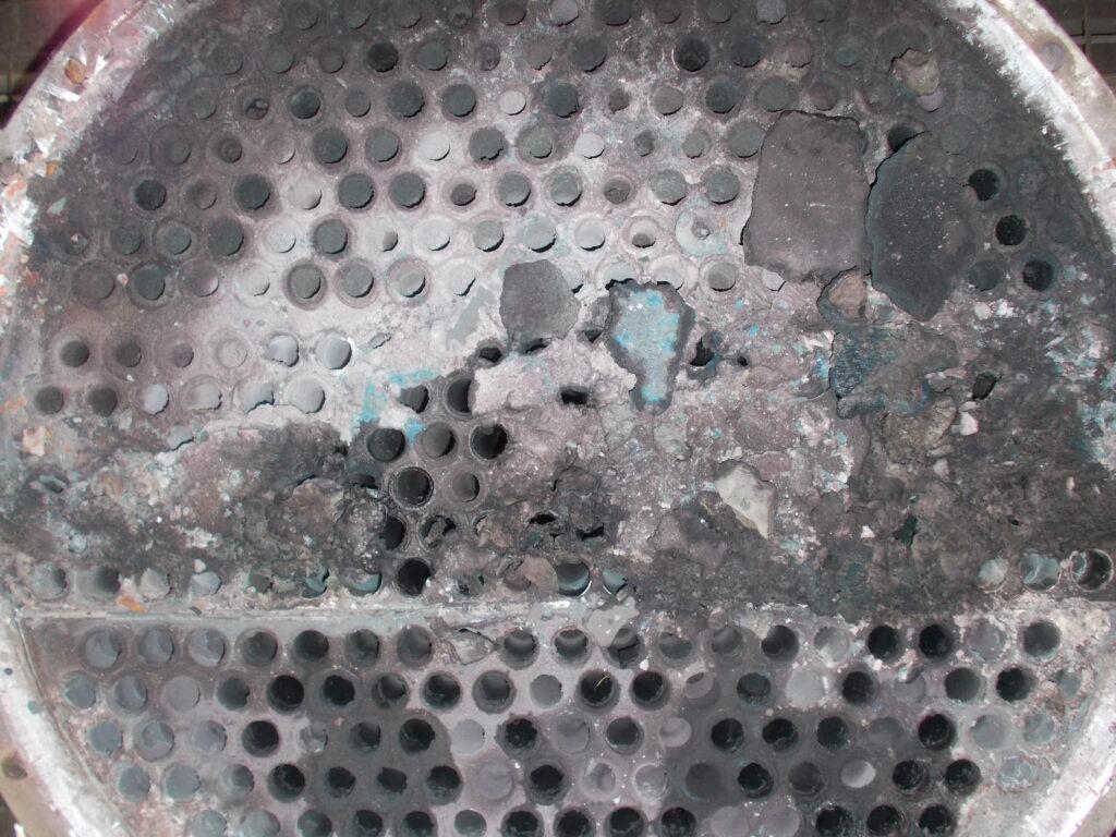
Figure 2; Fouling as experienced in evaporator of effluent from dye-stuff producer
Experience with self-cleaning in dye-stuff effluent treatment
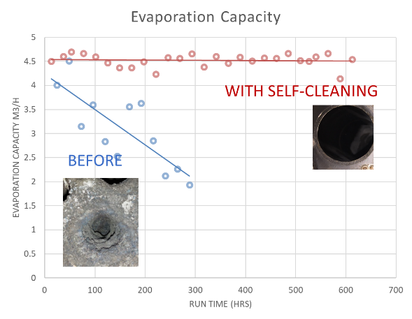
The effluent from a dye-stuff manufacturer characterizes itself by a combination of salts and organic components. When concentrating this effluent, the liquid develops a thick and hard deposit especially on the hottest tube wall being that of the first effect (as shown in the Figure 2.) Experience has shown that within 250 to 300 hours the evaporation capacity of a 4-effect evaporator had reduced with 50%. After retrofitting the first effect with the self-cleaning fluidized bed technology, the evaporation capacity remained constant over time. In this typical case, the fouling in effect 2 to 4 had always been less significant than that in effect 1, but it had reduced after the retrofit as well. Knowing the strong dependency on the exact liquid composition, the performance for a second evaporator plant of the same client but at a different site with a different effluent composition showed that introducing the self-cleaning technology solved the fouling in the first effect but the other effects still had fouling. Therefore, the evaporation capacity still reduced over time but at a much smaller rate increasing the average capacity and the time between cleanings.
Click on the image to enlarge
Figure 3; Evaporation rate MEE plant before and after the revamp of the 1st effect to self-cleaning
Design of a MVR, effect of liquid composition and fouling
The thermal design of a MVR requires careful attention with respect to the compressor performance, the composition of the liquid and the required heat transfer area. The compressor design and selection will determine the temperature increase given to the vapor and yields the driving force for heat transfer between the condensing vapor and the liquid at the tube side. The higher the temperature difference, the lower the required heat transfer area (HTA). On the other hand, the higher the temperature increase the more power the compressor will consume.
The required temperature increase will also depend on the liquid composition. The reason being that specifically salts increase the boiling point. This boiling point elevation (BPE) is lowering the temperature difference between vapor and shell. For example, if the vapor from an atmospheric evaporating system is 100°C, the liquid will boil at 108°C when assuming a BPE of 8°C. When the two-stage compressor gives a temperature increase of 16°C, the vapor will condense at 116°C. The driving force for heat transfer then roughly becomes 8 degrees. In case of a single stage compressor with temperature increase of only 8 degrees, no driving force would be left. The required heat transfer will linearly depend on the temperature difference after correction for BPE. When underpredicting the BPE, the chosen HTA could become too small affecting the capacity by tens of percentages.
Since fouling can easily reduce the coefficient of transfer with 20 to 50% or even more, the formation of scales can just as well have a detrimental effect on the evaporation capacity. This makes the self-cleaning system so attractive. It prevents overdesign and keeps the plant capacity constant.
Operational aspect using compressors
Operating compressors will require some attention of plant operation. When using root blowers, the equipment is more robust and the required attention is less than with turbofans. Turbofans have fast running impellers with high tip speed that are susceptible to vibration issues when the impellers get dirty. Monitoring the vibration and stopping the fan in time will prevent larger damages. When taking care of the compressor, experience has shown that MVR units have a good reliability.
Conclusion
So, to conclude, the self-cleaning evaporator using a MVR Evaporator is the way to go as to save on primary energy use when treating effluent and maximizing the potential of the self-cleaning heat exchanger technology.
KLAREN Technology Brochure Self Cleaning Evaporator
